Easy Electronics DIY Projects

Jump aboard the DIY Xpress, the forum for easy electronics DIY projects.
Welcome to all my beloved "boys" (and that includes the girls too!) who enjoy doing things.
Together let us get our hands on things and make them better...
... and better-suited to each of us!

Sunday, July 3, 2011

NOSTALGIA... EASY DOES IT !!

Recently while exploring a few cartons of 'valuable junk' stored away in the outhouse for the past few years, I 'unearthed' a rather quaintly named old gift from a good friend of mine. (Paulji, recognize the old beauty??)

It was the "Media Lite" (I haven't yet figured out where the 'media' fits in!) -- an old lantern with twin one-foot fluorescent tubes that put out a fair amount of light. The circuit was rather complicated, with twin inverters running off a 12 V battery, with provision for running either off the mains or as an automatic 'emergency' light when the mains failed. Perhaps its only weak point was that the batteries would conk out within about 15 minutes with both the tubes going, or a more practical half hour with just one tube running. The circuit, unfortunately, had no cut-out that might have saved the battery when its voltage fell to unhealthy levels.

Soon, like most battery-powered emergency lamps that are neglected till the season of power cuts, this too stopped working. Attempts at rejuvenationg the inverter circuit met with only partial success, and soon it joined the many other 'pieces of tech' that were gathering dust and cobwebs on a backroom shelf. But its association with my friend had persuaded me to 'save' it and put it into cold storage.

After a dusting and "gutting" of the wiring and the old PCB, I gave it a good 'bath' with a soft brush and some shampoo. The lantern emerged, well, almost as good as new.

Now here was a good candidate for LED conversion that would give it a second lease of life--surely my friend would love that! Of course, the basic design revolved around the popular LED strip, and a simple charging circuit for the battery. I wanted to retain the '1 tube/ 2 tubes' switching from the original lantern. That meant having two small pieces of PVC pipe with the LED strip wrapped around them. But I found that the better option was a larger diameter single pipe section


with two LED strips (the photo above shows only one strip now) wrapped in an interleaving helix, which gave better illumination and did not put any mechanical strain on the LED strips too, unlike a smaller tube. The original 12 V battery was available no longer, but as luck would have it, a couple of standard (cheap!) 6 V 'emergency lamp' batteries, connected in series, dropped into the battery chamber perfectly.


Again, in order to keep the circuit simple, for the present I have not used a mains failure auto switch-on. That meant it was an afternoon's work to wire up the circuit and 'commission' the lantern -- EASY!!

Surely this looks like an 'evolving project', and I would be happy to present some mods/additions in the near future. The full circuit and 'fully finished' phots will have to wait for another post as I had only about 1.5 M of LED strip in hand (just enough for one helix) and there was a shortage in the parts shops. You will find that helical winding will 'eat up' a good length of strip before you know it. Considering the 'precious nature' of the old lantern, I was in a hurry to have it switched on and enjoy the 'sweet light' from an old faithful!

Here is a picture of the working lantern and I am glad it is very bright and with one more LED strip added, it might well achieve the level of illumination of the original, though I have a feeling that the bright LEDs call for a diffuser rather than a clear 'chimney'.


The hobbyist is referred to the earlier posts regarding  the internal 'wiring' of the LED strip, electrical safety, --which is of paramount importance if one is to continue with one's hobby ! -- esp. where the circuit is connected to 240 VAC mains, etc.

Many of you are likely to have a couple of fluorescent tube-based old emergency lamps in your junk box. A conversion strategy could be based on my experience. The only thing to remember is that the LED strips that are available currently in the market are wired for 12 V, and that makes it mandatory to have space for two 6V batteries within the housing. However, once the old PCB is jettisoned, most lantern bodies would accommodate two batteries one above the other, I feel. Again, your ingenuity alone is the limit when it comes to breathing new life into an old lantern that might have some precious associations from the past.

Until the next post, happy conversions !!

* * * * * * * * * * * *

Tuesday, April 5, 2011

EASY BAMBOO TABLE-LAMP

It was while putting up some bamboo arches and frames for creepers in the garden that an idea occurred to me--why not try and make an easy "eco-friendly" table-lamp? It would make a nice 'Vishu' present to the "significant other" in your life too! You just can't beat the combination of energy efficiency and eco-friendliness, not to say anything about the less than shoe-string budget!

I just picked up a couple of pieces of bamboo offcuts, which, after cutting, was about a foot long. To go with our "easy" tag, I hit upon a simple shape that involved no "heavy engineering" or joints or pivots or other complicated stuff. The geometry was simple and somewhat like a vertical lamp-post, with the LEDs on a disc that was at 45 degrees angle so that it threw a good beam onto the table. The bottom portion housed the "electronics", while the base was sand-loaded for stability.

If you refer to the pictures, you should be able to follow the project easily. The top is cut off near the 'node', while the bottom cavity is larger to accommodate the sand that gives a heavy and stable base.

Now follow the photo and mark the 45 degree cut and the verticals to the bottom cut--be careful to mark the verticals along the 'grain' of the bamboo. Do the slant and the straight cuts with a small hobby hacksaw--be very careful about the end points. Now use a small chisel, or a sharp knife and a small hammer and cut along the verticals carefully. The chisel/knife going in will be enough to split the bamboo along its grain, and if you are careful, in a matter of minutes you will end up with two neat pieces.


Do have a look at the photos. I am sure your ingenuity will find a use for that "waste" piece of bamboo in another project.

Now clean and rub the inside of the bamboo piece (which forms the body of the lamp) with some medium sandpaper and leave to dry in the shade for at least a day. Now drill the holes for the mains cord, a small toggle on/off switch in the back  just above the bottom node. Cut a disc of phenolic /acrylic for mounting the LEDs and see that it fits the top 45 degree cut. Here it is best to mark it on a piece of card and then use it as a template to cut the acrylic. (Also mark and drill the holes for mounting the LEDs.) Now give a couple of coats of wood polish to the bamboo, inside and out. Once the polish has dried, take some clean, dry beach/river sand and fill the bottom cavity with that. Pour a thin layer of wood glue like Fevicol to seal the sand and keep it inverted until dry. Now stick a thin layer of foam to serve as a non-skid foot.

Wire up the mains cord, the on/off switch , the dropper cap, bridge etc and connect two small wires to the + and - outputs. Stick these wires to the back support vertically so as to reach the LED housing.  Now wire up the LEDs. I still recommed that you go for pulsed DC operation (and not for pure DC) as we have been doing for all our projects, as this gives a higher brightness and also some "rest" for the LEDs during the off periods. Wire 3/4/5 LEDs in series with a small series resistor of about 150 Ohms to 100 Ohms, and use as many such " strings" as you need to cover the LED holder disc. Naturally the size of the disc depends on the diameter of the bamboo you have chosen and this needs some careful planning. Now connect up everything and test. Once everything tests okay, fix the LED disc onto the bamboo body with some hot-melt glue. Cut off one node of a smaller section of bamboo to serve as a " press-fit lid" for the bottom electronics housing. You are finished!

The more resourceful DIYer might want to use a small torch reflector or something like that from the junkbox to house the LEDs. A fellow DIYer tells me he is planning to use a reflector and a 1 Watt "high-power" LED that he has (from a broken torchlight). I am sure you could come up with your own variations, as the basic design is sufficiently "open", and so your ingenuity is the only ruling factor.

Once the project is finished, put it in a "custom-made" cardboard box, wrap it up nicely and make a present of it to whoever is "significant" in your life. I would guarantee that the LEDs are sure to be less bright than the face of the recipient!

* * * * * * * * * * * *

Wednesday, March 16, 2011

EASY 'MOSQUITO' COMBO CONVERSION

The 'zero watt' night lamp project was very popular, with many DIYers enthusiastically pursuing conversions. While on the subject of 'conversions', let us look at another idea that was triggered by the needs of the mother of a newborn.

As we all know, in India, one of the hot-selling items is the electric "mosquito repeller", or, to give it its proper name, the electric vaporizer for mosquito repellent. Every household has three or four--if not more-- of these units and most of them are kept on throughout the night. Most of these units consist of little more than a ceramic heater element and a neon tube or LED power-on indicator, the whole thing built into a plug-pack.

The lady in question, a brand new mother, wanted a dim night-lamp. The usual 'zero watter' was too bright for her liking and she said the mosquito unit's 'on' indicator was too dim to serve any useful purpose. This gave me the idea to replace the neon or the solitary red LED with a couple of hi-brite LEDs. Of course, we know that it is an easy matter to 'tailor' the brightness by choosing a suitable 'dropper' capacitor. I decided on a two-LED configuration in order to keep the assembly simple and at the same time make use of both negative and positive swings of the mains AC waveform. Just have a look at the circuit/s and the modifications.

First of all open up your mosquito unit--usually a couple of screws in the bottom secure the two halves of the shell together. Be careful to study the plug-pin unit and its mounting to the assembly while disassembling. You will see the ceramic heater and sometimes a 'protector' NTC device wired together directly to the plug pins. The neon or the LED too will be connected to the same points through a series resistor. Please note that the heater gets really hot and so soldered joints will not stay put, and the original connections will be twisted or crimped. Use a sharp cutter and cut away the indicator's series resistor, leaving a few mm of lead for us to 'twist-connect' to. Do the same thing at the other end too while cutting away the neon or the LED.

Now study the unit and plan how you are going to mount the LEDs. Usually they do not need any "mounting". You can follow the example shown and evolve your own method. I soldered together two LEDs back-to-back--that is joined them together with the + lead of one to the - lead of the other and the - lead of the first to the + lead of the second. This is how they looked, with one lead each left uncut for connection to the series resistor and the dropper cap/bleeder resistor combo, respectively.

This made it convenient to wedge the LED assembly to a vertical 'holder' moulding that originally held the neon indicator tube/LED. Check the photo for the details. This meant that ample insulation was also there between the leads and the LEDs faced up, throwing their light onto the ceiling. The diffuser of the unit does not "diffuse" the focussed LED beam that much, and I found that it was best to mount the LEDs facing up. You may try your own "trial and error" methods here for mounting/direction of the LEDs.

I chose a 0.1 uF/400V dropper capacitor and a 1k Ohm/half watt series resistor. After twisting and soldering the bleeder resistor onto the cap leads, check the "measurements" by placing the LED assembly, the cap etc into the shell and then cut the leads to give you enough to 'twist-mount' the parts. Crimp or twist one end of the dropper cap to the heater terminal lead stub (that you had left conveniently cut earlier). At the other heater terminal, crimp or twist-mount the 1 k Ohm resistor. Now mount the twin-LED assembly suitably and cut the leads so that you can comfortably twist the two ends of the LED assembly to the capcitor lead and the resistor lead on either side. The leads will be rigid enough to keep the assembly safely in position. Test by plugging in.

The LEDs should light up and the heater should heat up. Once everything is satisfactory, use minimum solder and solder up all the twisted connections to preclude oxidation of the twisted contacts over time. Reassemble the shells together carefully and you have a nice combo mosquito unit/night-lamp for the bed room or the child's room--or anywhere else you might want to have some dim 'romantic' lighting!

So get a couple of LEDs and resistors and a capacitor, and open up that mosquito unit -- ASAP!


* * * * * * * * * * * *

Monday, March 14, 2011

EASY 'ZERO WATT' SAVERS

That project title could easily qualify as an 'oxymoron'-- an expression with apparently contradictory terms/ ideas appearing together. But from our DIY angle in the Indian context, we are, I believe, justified fully! Read on to find out where the saving comes in and what the zero is about.

A recent "power audit" at my home and my sister's place sort of "opened my eyes". I came across many situations when the little drops would over time make up, if not an ocean, at least a fair-sized swimming pool or a large pond. I am sure your experience too may not be far from mine.

In many  households it is a practice to keep small lamps burning continuously in the 'puja' room, surely before the pictures/icons of gods and goddesses, not to speak of the photos/paintings of our long-departed beloved relatives. Usually the choice here falls on small coloured bulbs. Another common practice is to have a small night lamp burning throughout the night in bedrooms, particularly those of children. Here also the choice is mostly small bulbs. These bulbs are usually referred to as "zero watt" bulbs as their consumption is "ridiculously low", according to the makers and the shopwallahs.

This might have been so in the good old days of the analogue electricity meter, which needed some healthy current flowing thorugh it to start it running. Not so now in these days of the electronic utility meter that registers even minuscule amounts of current. I checked a number of "zero watt" bulbs and found that ALL of them consumed between 3 and 5 Watts! So a few "zero watt" bulbs burning throughout or at least through the night would, at the end of the second month when the electricity meter reader comes, easily add up to a few units-- one 5 W bulb running for about eight days or about 16 nights would 'eat up' one unit of power.

This, then, was the trigger for me to try something new to save some of those "zero watts". By now I am sure most of us have become adept at using LEDs wherever low-light applications are called for. Nobody is going to stop you from taking a few LEDs and wiring them up as a "zero watt" bulb replacement or as a night-lamp, following our 'standard' circuit. But that is all old hat! So here let us take a look at an EASY, NOVEL solution with a minimum parts count too.

A look at our 'standard circuit' reveals the dropper cap and bleeder resistor, the bridge rectifier and the LEDs and their current limiter resistors. When we used the ready-made LED strips, the strip contained the current-limiting resistors too. As this is a low-light application, we will use smaller values for the dropper cap, and use just a few hi-brite LEDs.

Hey, hey, aren't LEDs Light Emitting DIODEs? That gives us a novel idea! Throw out the bridge rectifier diodes and use four LEDs instead, and use one or two more LEDs as the "load"! That should give us five or six LEDs and enough light as a "zero watter" or as a night-lamp.

The AC mains gives us alternating current which from zero rises to a peak and then falls to zero and goes to a negative peak, then back to zero, with the peak voltage going up to about 1.4 times the average value of 230 Volts. Looking at the bridge rectifier, we can easily see that on positive cycles current flows thorugh one leg of the bridge to the 'load', and completes the circuit through the other leg of the bridge. On negative swings, it is the other two legs and the 'load' that conduct the current. Just follow the arrows on the diagrams below and things will be clear to you.

This means that with an all-LED setup, on positive swings, two diodes of the bridge legs will be lit, along with the 'load' LED; on negative swings, the other two LEDs of the bridge and the 'load' LED will be lit. That is to say, the 'load' LED will be lit continuously (I am ignoring the pulsed drive here --not DC--for simplicity), while 'one half of the bridge' will "flicker on" only when those diodes conduct. In practice this is not going to make much of difference as the 'load' LED will be brighter and will keep the average light at a higher level so that you don't notice the flicker. If you look through a digital camera, its CMOS sensor will make the flicker easier to see.

I have redrawn the circuit so that it resembles the physical layout, and the photo shows the wired-up version with just one 'load' LED. Be sure to watch the LED polarities as you have to be careful to get it right. Again, check the drawings. The 'load' may be one, two or three LEDs depending on your brightness requirements. Also, "fine tune" the value of the dropper cap, beginning with a 0.22 uF/400V one, as otherwise the lamp is likely to be too bright.

It will be a cinch to wire up "self-supporting" LED arrays and put them into night-lamp mouldings and into decorative plastic fittings to make "zero watters". Be sure to use small lengths of plastic sleeving over bare leads of LEDs etc and pay attention to insulation and safety while "playing with" mains voltages.

Let us 'zero in' on those zero watters!

* * * * * * * * * * * *

Thursday, March 10, 2011

EASY LED 'BULB'

I can see a lot of eyebrows going up on seeing the title of the project.

Aren't bulbs passe?
Sure, they are; but...

The recent International and National campaigns to replace the incandescent bulb with a more energy-efficient alternative is fresh in our minds. The good old electric bulb has been with us all along right from the days of Edison, the original inventor of the incandescent bulb. Over the decades it had held its own--it was simple, inexpensive and universal. Only that it was not energy efficient, especially when compared to fluoresent tubes and their smaller cousins, the CFLs. Today it is not easy to locate a bulb in an average household as a result of the 'replace the bulb' campaign.

Looking forward to the future, we can easily see that it is the era of the LED, which is even more efficient than the bulb and the CFL, its life is phenomenally longer and it runs cooler, it can work at very low voltages directly, and overall it is more reliable. Then why haven't LED lamps replaced the bulbs and the CFLs? High cost is the factor that has kept the LED lamps from being very popular.

A look at the local market reveals that 'drop-in' LED replacements for the bulb are available, but they are pricey, Indian ones going for about Rs 700 plus and cheaper Chinese imports going for about Rs 300 and up. And frankly, many of them are not bright enough, nor are their 'beam patterns' suitable for replacement in standard lamp shades. The right time for the DIY guy to try his hand.


Here is an LED 'bulb' that is inexpensive and works in most common lamp shades as the LEDs are deployed in 360 degrees. Above all, like most of our projects, this is EASY! In fact it is one of the easiest and cheapest of projects, as a 1 metre strip of LEDs and a few components are the only things you need to purchase.

HANDS-ON

Retrieve an old fused CFL from the junk box. Disassemble it and discard the glass tube part carefully. Unsolder the leads from the bayonet holder to the small PCB. You will see a bridge rectifier (four mains-rated diodes) right where the AC goes in. Either remove the diodes, or better, remove all the other components and retain the bridge on the small round PCB. Refer to our strip-lamp circuit and connect the 0.47 uF cap + bleeder resistor to one side of the bridge. The free end of the "dropper cap" can be wired to any small PCB pad and now you can wire up one of the AC mains inputs from the bayonet holder to that pad and the other AC wire from the bayonet socket to the other corner of the bridge. Remember, there is no switch here.  Wire up a black and red wire each to the + and - outputs of the bridge to feed the LED strip.

Now look around in your junk box (or ask your friendly plumber!) for a suitable diameter PVC water pipe that fits into the top part of the CFL housing. Wind the LED strip around this in a spiral and note how long a piece you would need. Refer to the pics and finalize your assembly. I have used a couple of screws so that it can be disassembled easily for trying various caps etc. Once you have tested and finalized everything, the best deal would be to use hot-melt glue and stick it together. A small hole is drilled through which the +/- wires are fed and soldered to the strip.  It is better to solder the leads before sticking the LED strip down. Do it fast with pre- tinned leads and take care not to overheat and melt the strip into goo! Now mark the first spiral with a scratch on the PVC pipe.

Now clean the PVC pipe with detergent and dry it thoroughly, and see that you don't get grease on it by touching it. Remove a few inches of the adhesive backing paper from the LED strip and carefully align the first spiral to the mark made earlier and begin sticking down the strip. As you go, continue to remove the backing paper and carefully stick the rest of the strip to the PVC pipe. See that this is where your "artistry" has to come into play! You will be amazed to see the whole 1 metre of the strip occupying a length of hardly 3 inches of pipe. Put a small glob of hot-melt glue at the end of the strip and seal the small hole for the wires at the other end too.

Connect up everything, either screw together or better glue together the byonet holder part and the PVC pipe section, seal the bottom of the pipe with a disc of plastic or laminate or even thermocol to keep out the pests. Remember to drill a few small holes in the disc, which, along with the holes in the base of the holder, assures some ventilation for the circuit. That is all!

Push it into a lamp shade, and switch on, and you have got onto the Energy Star bandwaggon with a state-of-the-art LED 'bulb' !!


Build as many as you want for your low-light needs and surely you will save some money and also reap a lot of satisfaction. In case you want a longer 'bulb', it is only an easy matter to add another half a metre or even one more metre of strip and use a suitably longer pvc pipe. If you want a stouter bulb, use a larger diameter pipe and use a "reducer" available from plumbing suppliers and glue the holder part at the end of the "reducer". This will make it easier to have a couple of metres of LED strip on a short and stout piece of pipe. As I said earlier, your imagination would suggest many more designs to you to meet your varied needs.

Now's the time to replace those bulbs with better 'bulbs' !!

* * * * * * * * * * * *

Wednesday, March 2, 2011

EASY DISCRETE-LED MOUNTS

Once an idea is mooted, the "boys" want proof of concept! Thank you for your enthusiasm.
Here is a small assortment of discrete-LED mounts adapted for commercial lamps and fittings.


The first is a personal favourite. An old CFL table-lamp had reluctantly been consigned to the 'junk box'. It was retrieved, cleaned up and the insides removed. I retained the old heavy choke or ballast purely as "ballast" to keep the lamp steady with its weight. A small piece of parallel-track PCB was cut and fashioned to fit into the lamp housing and the LEDs and resistors were wired up. The original switch was retained and the capacitor/bridge rectifier assembly was kept in the base and insulated well from the heavy iron and copper ballast. As the lamp "joints" move a lot while the lamp height is adjusted, good quality thin two-core jacketed mains wire was used for connection from the bridge to the LED PCB. Screw everything back together and you have that favourite old lamp in a new energy-efficient and cool-running 'avatar'! The technique could be adapted to modify virtually any table lamp that you have.


The second is a 'dome light' at home that stays switched on from evening till midnight, which makes it a prime candidate for LED conversion. The photo shows the acrylic LED mount and the glass dome diffuser. As it needs to put out a 'decent' amount of light, LEDs were 'lavished' on it. A piece of acrylic, cut to fit inside the housing is marked and drilled for the LEDs. It is best to do all your planning and drawing on a piece of graph paper to make it easy. Then stick the paper to the acrylic sheet with glue (it will peel off easily) and then drill it carefully. The photo shows an early 'proto' sheet that broke while drilling. If your lamp assembly is small, you could even use a couple of waste CDs (perhaps DVDs will be more 'mod'!) stuck together with superglue for thickness and strength as the LED base. (A good gesture from the angle of recycling too! ) Be careful, as always, about clean wiring and soldering and insulation. Mount the assembly into the lamp and wire it to the domestic wiring using a 2X screw connector strip. Put on the glass dome, and the diffuser will give a smooth spread of light.


The third project tackles the conversion of a tubular hanging lamp with a spotted glass cylindrical shade. This called for a tubular mount for the LEDs. A short piece of 2 inch PVC water pipe does duty nicely here. The pipe is split in the middle into two so that the LEDs could be wired up easily. The two halves are wired up and tested as independent lamp assemblies and after rolling up a piece of plastic sheet (from an old file or so) as an insulator, the halves are joined together with tape or a couple of rings of plastic pipe that have been heated and pressed on. Remove the 'bayonet' fitting from a discarded CFL, connect up the wires and stick it to one end so that you could put the LED 'bulb' on just like a regular bulb or CFL into the lamp fitting.

Hope this gives you enough ideas to trigger your imagination. As I said, your imagination is the limit, and your care and craftsmanship will give a 'pro' finish to your handiwork, turning it into a "designer lamp". Remember to mail me your notes and pics so that I could post them here.

Gentlemen, start your drills!

* * * * * * * * * * * *

Monday, February 28, 2011

EASY MODS for the LED-strip Lamp

It is heartening to note that the LED strip lamp project has struck a positive chord with many hobbyists. Surely when compared with the few commercial products available at a steep price, the project is attractive both from the cost angle as well as from the ultimate saving one will make by way of reduced power bills.

Many had requested  the incorporation of a 'Hi-Lo' switching, so that the lamp could be kept on for dim 'mood' lighting and then switched to full brightness. I too thought this would be great, especially when  it is used as a 'wall-washer' or 'ceiling-washer' lamp above the TV.

Keeping to our motto of 'simple and easy', we will look at a solution. You might recall that 0.47 uF cap gives you about 47 mA current. Suppose you want to cut the current/brightness to half, go for a cap of 0.22 uF/400V, which gives you 22 mA. Please note that brightness and current do not have a one-to-one relation; the best way is to try various caps and then decide on "your brightness" and then wire that value in.

Incidentally, caps come in standard values of 0.47uF, 0.33uF, 0.22uF and 0.1uF.

Now for the Hi-Lo switching. Hunt around the electronics market and you are likely to get a mains-rated switch, either a rocker or more likely a slider, with a 'centre-off' position. If you do, consider yourself lucky and get that. Replace the original on/off switch with the new one. Look at the figure (A) and modify the wiring, and you are in business in no time!

Suppose you dont get a 'centre-off' switch? Go for a small rocker or toggle on/off switch, again rated for mains voltages. But this time you have to drill another hole or a slot near your on/off switch to mount this hi-lo switch. Wire it up looking at the diagram here (B) so that when the switch is closed, it adds a larger cap in parallel to the low-value one in circuit, which determines the low brightness. Please note that caps in parallel add up in value and so 0.1uF and 0.47uF will give you 0.57uF, pushing up the current to 57 mA.

The values I have suggested are typical ones. Surely they need some 'tweaking' and individual requirements will vary, depending on where you mount the lamp, the reflectivity of your walls/ceiling etc and your own 'level' of preferred low brightness. In the event that even with a 0.1 uF Low cap, you find that the lamp is bright, buy one more 0.1 uF of the same sort and put them in series. This will give you 0.05 uF and about 5 mA of current, but will push up the voltage rating of the 'total cap' to double that of the individual cap- a good ploy to prevent transient high voltages from 'eating' your cap.


I anticipate 'control freaks' going in for a multi-way switch and playing with a number of caps so that they  will have brightness levels that could be "dialled in" to suit any mood! Bravo to them, with the caveat that any switch you use should be capable of safely handling mains voltages.

Gentlemen, start switching...

                                         * * * * * * * * * * * *

Sunday, February 27, 2011

EASY LED-STRIP LAMP


Soaring electricity charges and eco concerns have made many of us extra conscious of the need to use less energy. Of late we have been hearing a lot about the economy and long life of LED lighting, though they were often an expensive solution. The familiar Light Emitting Diodes are totally solid-state devices like the transistor which emit light when a low voltage is applied to them. They, unlike the incandescent bulbs, dont have any hot filament inside them to burn out or need high voltages like the CF Lamps, or their larger cousins, the common "tube lights".

Today a variety of LEDs in all colours, including blue, (which had evaded scientists' efforts till recently) have flooded the market. Popular are the white "hi-brite" LEDs which output usably bright light at a very low current of just a few tens of milliamperes. These days on the roads you get to see LEDs on a lot of cars and bikes as fancy decoration, and today you can buy/build LED replacements for brake lights, car interior lights etc, though high power LED headlights still are prohibitively costly.

Looking at what can be accomplished using LEDs available in the hobby market at average prices opens up various possibilities. In most homes our need is for general low-intensity lighting for most of the time. When we move to specific tasks, say like, cooking, eating, reading etc, we can switch to brighter "task lights". If you look at an LED you can see that they 'beam' their light in a narrow angle, and side scatter is very low. This property comes in very useful when you consider tasks such as viewing TV or working on the computer , where the light should not spill onto the screen, yet the keyboard should be clearly visible. The low power of the LED makes it easy to run it from the computer UPS so that you are not plunged into darkness the moment power fails. (I am not forgetting the extra bright CRT computer monitors that were very good "emergency lights", though they "ate up" the UPS battery fast.)  Today it is an easy matter to "cobble together" a quite good mains LED strip light at a reasonable cost and with a minimum of effort. We shall look at various "options" also to suit your individual requirements.

As I said earlier, LEDs work at very low voltages-- a couple of AA cells in series giving about 3 Volts or a Lithium "button cell"  will light up virtually any LED. A word of warning though--for 'testing' an LED it is okay to very briefly touch an LED's leads to the battery, but dont keep it lit without putting a small resistor in line with the LEDs, or the excess current will kill it in no time. This being a "hands-on" column, we will look at how to do things and look at the "theory" part later. I assume you have at least a small soldering iron (and good quality solder, and also that you are good at soldering well!) and other hand tools like scredrivers, pliers etc.

HANDS-ON

Now for the shopping list. LEDs first. Strips of pre-wired LEDs on a flexible printed circuit, complete with series resistors and an adhesive backing, are available now in most hobby electronics shops. This is the kind you see often on cars and bikes. Two varieties were available when I checked last--a plain strip and another with a water-proof gel coating. For ordinary use inside rooms, we need just the plain, cheaper variety. A 50 cm length would be ideal as it can be easily built to look like a 2-feet 'tube light'. Two lengths of 50 cm strips side by side will give you twice the brightness. So buy half a meter or one meter as your budget permits. Check to see that you are getting the bright, white or warm white (slightly yellowish, like Sodium vapour lamps) LED strips--at the shop they will test it for you after cutting a length. Buy four mains rectifier diodes of the 1N 4000 series, a couple of resistors of 470k or 560 k value and a good quality mini-rocker mains switch.

Now select a few good quality high voltage capacitors. Buy dependable brands and dont scrimp here --these are critical components that come under a lot of stress and we dont want them to break down easily and vapourize everything. Minimum voltage rating is 400 Volts, though it will be great if you could get 600 V. But generally they become larger the higher the voltage rating gets. Dont buy cheapos here. The values to go for are a couple of 0.47 uF and a 0.68 uF. While you are at the shop, get some lengths of plastic sleeving too for covering the "hot" (high voltage) leads for insulating them.


Now for a housing for your tube light. It may not be easy to get spare plastic housings made originally for fluoresent strip lights--if you can beg, borrow or steal (!), they are ideal. ( I was lucky to have an old friend, 'Wintek' Suresh, hobbyist and manufacturer of audio and other hobby kits, fluorescent lamps etc, who very kindly gave me a few housings for CFLs complete with diffusers--this contributed to the 'pro' finish of the project. Thank you, Suresh!)

 If not, walk into any electrical store and ask for a length of " cap and casing" wiring conduit, which is a click together, two-part plastic channel for household wiring. While there buy some good two-core wire and a two-pin plug for your lamp. Now you are all set to begin.
Examine the flexi strip of LEDs. The ones I looked at have three LEDs and a resistor wired together in series between the marked + and - prints. All the sets of three LEDs plus resistor are connected in parallel to the + and - tracks. Look at Fig 1 to get an idea. The black rectangular things are the resistors and they will have a value printed on them; 151 means 150 Ohms (that is 1, 5 and one zero), 221 is 220 Ohms and 331 is 330 Ohms. The lower values will give you higher currents and greater brightness. So check before buying if you have a choice. Otherwise dont worry too much. LEDs are polarized devices, though unlike a transistor, they will not be damaged if you reverse the connections, provided the voltage is low.

The circuit is extremely simple. But first, a serious word of WARNING. Whenever working with high mains voltages, give priority to safety, as otherwise it can be dangerous. Though the LEDs work at a low voltage, the circuit is "hot" and carries high voltages and are dangerous. Pay particular attention to insulating hot leads, covering everything in an insulating plastic enclosure etc.

{{{ EXTREME CAUTION IS ADVOCATED AND STRESSED!! }}}

If you want to light an LED you have to put a resistor in series to limit the current and bring it down to its working voltage and current. Suppose you are lighting an LED from a vehicle battery of 6V of 12V, you need only a small resistor in series. But when you are applying 230V AC (which will go nearly as high as 230 x 1.4 times at its peak) you will need to put a huge series resistor. But resistors dissipate energy as heat and this is wasted power. We are lucky we have AC mains; we can use the property of capacitors that offer a "resistance" to the flow of alternating current in order to do the work of a resistor without wasting energy as heat.

What you see in the circuit after the mains plug and the switch is the "dropper" capacitor, with a "bleeder" resistor in parallel, so that whatever 'charge' is held in the capacitor is bled away to protect the user if he touches the plug leads after it is pulled out. A higher value cap will give you higher current and higher brightness--but dont think of raising the value higher and higher to get fantastic brightness!  There are other factors involved here and so we have to work within limits.

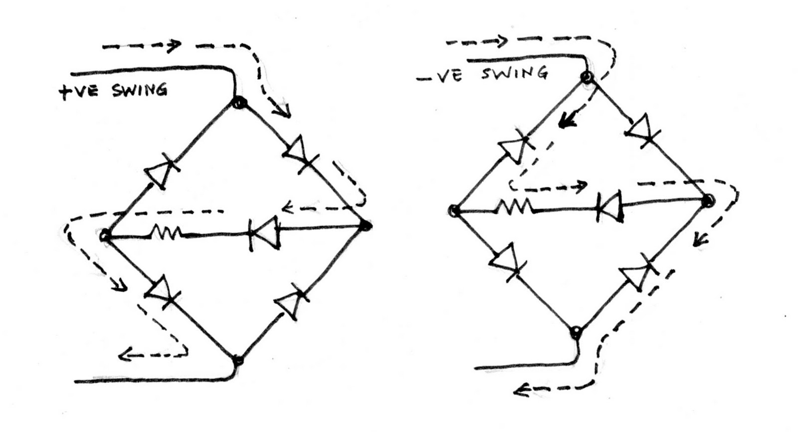
Now wire up the four diodes into a bridge rectifier--careful about the diode polarities and be sure not to overheat them. Good soldering requires that you practice heating the components to be soldered and applying the solder, all in one brief instant. Do not attempt "painting" with hot solder as it will not give you reliable connections. Cleaning and tinning the individual leads earlier will make soldering easier.

The four-diode "bridge" rectifier converts the AC into DC; watch the polarity of the output, preferably connecting a red wire to the + and a black/blue wire to the -. Note that we are not using a filter capacitor here at the output, and so we get pulsing DC here, as we want to take advantage of the peak pulsing currents at the output to drive the LEDs.

Now make cutouts on the side of the plastic channel for the switch as also small holes for taking out the wires to the LED strips, taking out the mains wire to the plug etc. If the mains switch is a two-pole model, it will, when off, isolate both the live and neutral wires.  But dont worry if the switch is a single-pole unit, as we will insulate everything safely.We will also seal the ends of the channels with pieces of rubber--an eraser often will be ideal, or you can ask for an offcut from your local cobbler.

Now trim the +/- wires to the correct length and solder the ends to the flexi LED PCB, + to + and - to -, taking care to do the soldering in "less than a second". Carefully remove the backing and stick the LED strip in a straight line onto the channel top. If you are using two strips, be sure to have two extra +/- "pigtails" at the ends of the connection wires for the second strip.

Check all the connections and be careful about the high voltages and see that you have connected up the 0.47 uF cap in series temporarily. Now carefully switch on, and the LED strip should light up. If all is satisfactory, change the cap to 0.68 uF and see that you have more current and higher brightness. It is better to do these changes at night when you can judge the brightness easily. Use the strip with one value for some time and then change to the higher value and use it for some time and see. If you have a 150 Ohm resistor in the strip, go no higher than 0.68 uF. You can also try putting the second 0.47 uF cap in parallel with the first which will double the current. The 0.47 cap at 230 VAC will permit a peak current of 47 mA or an average of 33 mA, which is well within the rating of average LEDs. Try the various cap values with caution and see that you get a satisfactory brightness. Put a small piece of double-sided cello tape to hold the cap to the inside of the channel, tidy up the wires, close the channel halves and seal the ends of the channel.

You may use double-sided tape to hold the strip lamp say, to the bottom of your computer shelf above the monitor so that the light shines onto the keyboard correctly. The lamp can also be used for general lighting in a room, and with an old UPS, it will give hours of light during power outages. If turned towards the white ceiling, it will give a pleasant overall light, especially in a child's bedroom. It can be used as cupboard lights, lights for stairs/steps etc. Your imagination is the only limit, but the power saving will be considerable if you are able to replace a light that will be on for a long time with an LED strip.

MORE  HANDS-ON

Those adventurous souls who derive a lot of satisfaction from "home-brewing" as much as possible have other options. They could buy a few dozen 'hi-brite' white LEDs, drill a neat set of holes in one half of the plastic channel, wire up one set of three or four LEDs and a small 100 Ohm or 150 Ohm resistor in series, do the testing with different caps and resistor combinations for a best compromise, and then wire all the sets of LEDs and resistors(with the selected values). Then connect up all the sets together using red/black wires, and finally to the bridge rectifier output, as we did for the ready-made strip. Use Fig 1 as a guide here. For best peak brightness and efficiency, it is best to limit each series string to a maximum of four LEDs and one resistor. Be careful to watch the LED polarity and be neat and tidy in wiring and soldering. Your skills and care here will insure safety and long life for the lamp.

The handymen among us will be able to dream up custom housings and diffusers for the lamps, turning then into "designer lamps". Again, if  you can do good soldering, you can experiment with individual LEDs arrayed in different shapes so that they can fit into conventional light fittings. You may use a plastic /acrylic sheet or laminate and drill suitable holes to hold the LEDs. Neat and well-insulated wiring is crucial. Surely the completed project will give you, in addition to savings, a lot of satisfaction every time you switch it on.


Let there be light!
* * * * * * * * * * * *