A recent "power audit" at my home and my sister's place sort of "opened my eyes". I came across many situations when the little drops would over time make up, if not an ocean, at least a fair-sized swimming pool or a large pond. I am sure your experience too may not be far from mine.
In many households it is a practice to keep small lamps burning continuously in the 'puja' room, surely before the pictures/icons of gods and goddesses, not to speak of the photos/paintings of our long-departed beloved relatives. Usually the choice here falls on small coloured bulbs. Another common practice is to have a small night lamp burning throughout the night in bedrooms, particularly those of children. Here also the choice is mostly small bulbs. These bulbs are usually referred to as "zero watt" bulbs as their consumption is "ridiculously low", according to the makers and the shopwallahs.
This might have been so in the good old days of the analogue electricity meter, which needed some healthy current flowing thorugh it to start it running. Not so now in these days of the electronic utility meter that registers even minuscule amounts of current. I checked a number of "zero watt" bulbs and found that ALL of them consumed between 3 and 5 Watts! So a few "zero watt" bulbs burning throughout or at least through the night would, at the end of the second month when the electricity meter reader comes, easily add up to a few units-- one 5 W bulb running for about eight days or about 16 nights would 'eat up' one unit of power.
This, then, was the trigger for me to try something new to save some of those "zero watts". By now I am sure most of us have become adept at using LEDs wherever low-light applications are called for. Nobody is going to stop you from taking a few LEDs and wiring them up as a "zero watt" bulb replacement or as a night-lamp, following our 'standard' circuit. But that is all old hat! So here let us take a look at an EASY, NOVEL solution with a minimum parts count too.

A look at our 'standard circuit' reveals the dropper cap and bleeder resistor, the bridge rectifier and the LEDs and their current limiter resistors. When we used the ready-made LED strips, the strip contained the current-limiting resistors too. As this is a low-light application, we will use smaller values for the dropper cap, and use just a few hi-brite LEDs.
Hey, hey, aren't LEDs Light Emitting DIODEs? That gives us a novel idea! Throw out the bridge rectifier diodes and use four LEDs instead, and use one or two more LEDs as the "load"! That should give us five or six LEDs and enough light as a "zero watter" or as a night-lamp.

The AC mains gives us alternating current which from zero rises to a peak and then falls to zero and goes to a negative peak, then back to zero, with the peak voltage going up to about 1.4 times the average value of 230 Volts. Looking at the bridge rectifier, we can easily see that on positive cycles current flows thorugh one leg of the bridge to the 'load', and completes the circuit through the other leg of the bridge. On negative swings, it is the other two legs and the 'load' that conduct the current. Just follow the arrows on the diagrams below and things will be clear to you.
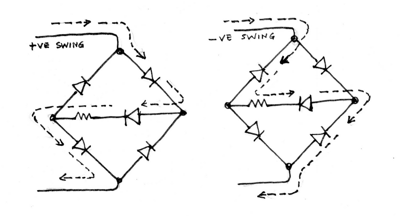
This means that with an all-LED setup, on positive swings, two diodes of the bridge legs will be lit, along with the 'load' LED; on negative swings, the other two LEDs of the bridge and the 'load' LED will be lit. That is to say, the 'load' LED will be lit continuously (I am ignoring the pulsed drive here --not DC--for simplicity), while 'one half of the bridge' will "flicker on" only when those diodes conduct. In practice this is not going to make much of difference as the 'load' LED will be brighter and will keep the average light at a higher level so that you don't notice the flicker. If you look through a digital camera, its CMOS sensor will make the flicker easier to see.

I have redrawn the circuit so that it resembles the physical layout, and the photo shows the wired-up version with just one 'load' LED. Be sure to watch the LED polarities as you have to be careful to get it right. Again, check the drawings. The 'load' may be one, two or three LEDs depending on your brightness requirements. Also, "fine tune" the value of the dropper cap, beginning with a 0.22 uF/400V one, as otherwise the lamp is likely to be too bright.

It will be a cinch to wire up "self-supporting" LED arrays and put them into night-lamp mouldings and into decorative plastic fittings to make "zero watters". Be sure to use small lengths of plastic sleeving over bare leads of LEDs etc and pay attention to insulation and safety while "playing with" mains voltages.

Let us 'zero in' on those zero watters!
* * * * * * * * * * * *
When are you guys going to post your comments and requirements and ideas??
ReplyDeleteVery useful circuit. Thank you sir. Excellent Work.
ReplyDelete